
Robust Rotary Encoder Logic (FSM)
Why an Encoder?
For the testing stages of the P.B. (Prototype Bot), I wanted to use an encoder alongside a joystick module to control the three motors. Keeping with the theme of the P.B. project, I researched what was going on under the hood of this module, and wrote custom code.
KY-040 Rotary Encoder
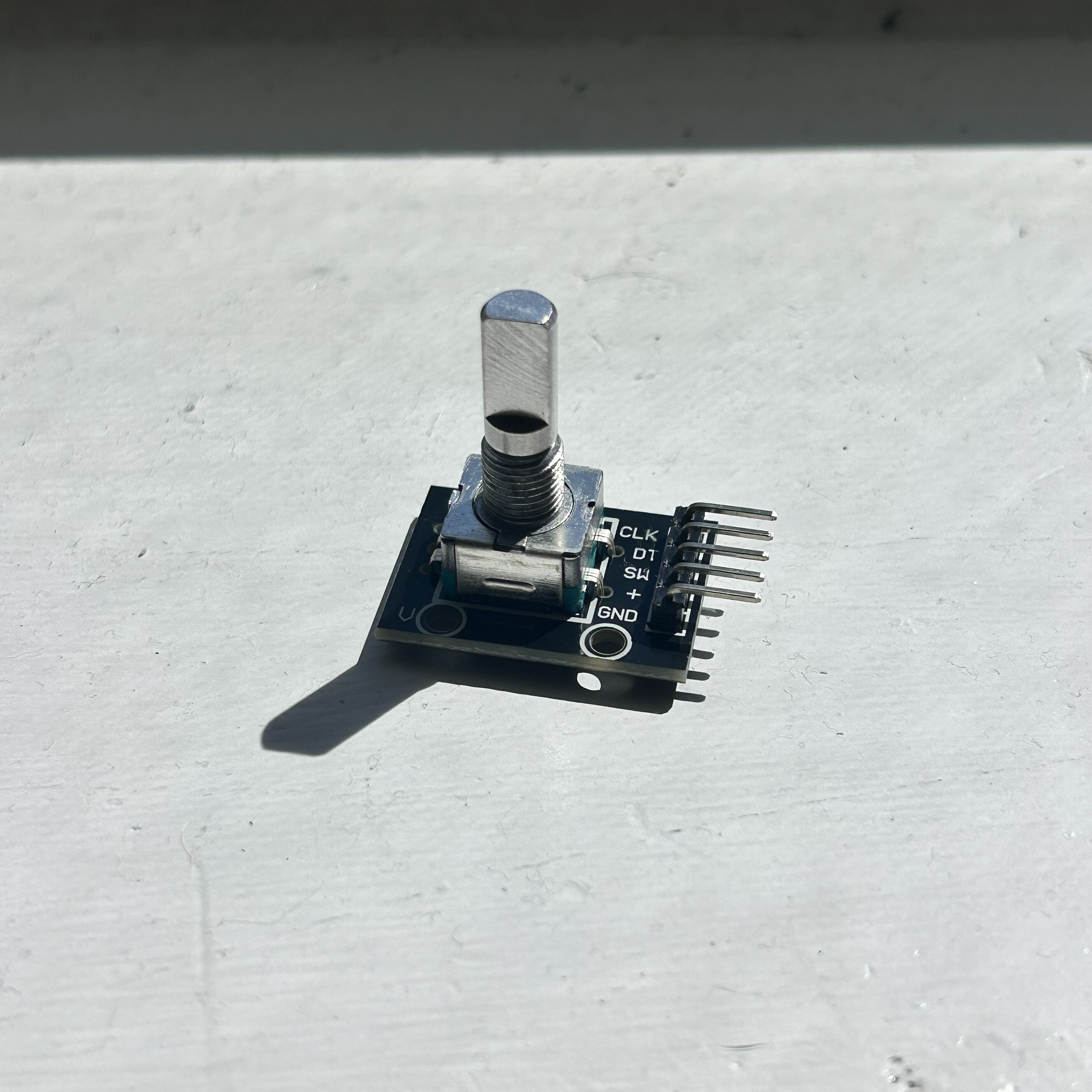
This encoder is pretty standard for beginner sets and came in my Elegoo Mega Project Kit. It has 20 increments per rotation and 5 pins. There is a tactile “click” between the increments. When I first plugged it in, I realized that I really had no clue how to track rotation. There was nothing on the module that gave the arduino “rotated 2 times” or “turning clockwise”. There were only HIGH and LOW signals from the CLK and DT pins. With amazing diagrams from HowToMechatronics I was able to test and understand exactly how an encoder tracks rotation.
How it Works
5 Pins:
- CLK: Channel A “Clock”
- DT: Channel B “Data”
- SW: Switch (not used here)
- VCC: +5V
- GND: Ground
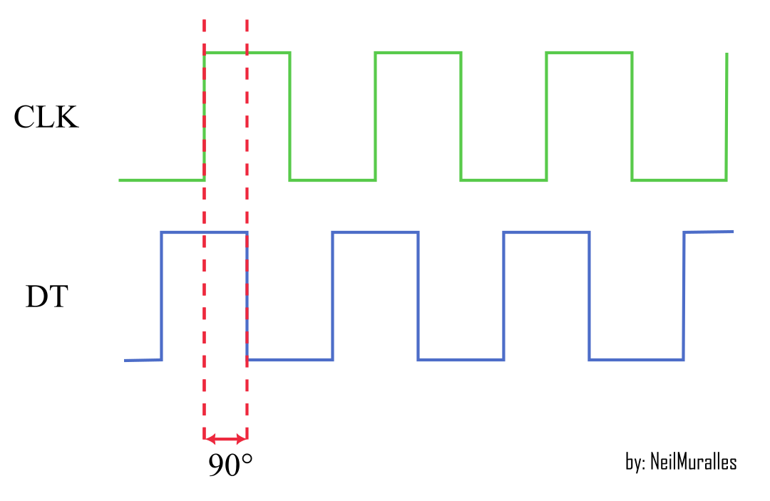
The VCC and GND power this active device and will interact with the CLK and DT pins. There is a disk that rotates when you turn the knob on the encoder; this disk has conductive contact zones along its circumference as well as nonconductive portions. The CLK pin and DT pin are both contacts that touch both the conductive and nonconductive parts, with the DT pin being 90 degrees out of phase with the CLK pin. In other words, when one switch changes from high to low or vice versa, the other switch is halfway through its own high or low state. Using pullup resistors, the pins return 0 (LOW) if the pins are contacting the conductive portion which is grounded and 1 (HIGH) otherwise.
This helps determine both if the encoder is rotating and which direction it is going based on which of the two contacts changes values at first.
Reading Issues
In between increments, or tactile “clicks”, the neutral state is [1,1] with both pins touching nonconductive sections of the disk. At first, I based my code on whether either CLK or DT changed values first and then made that the determining factor of motion. This is also common online, however there are a couple major issues with it.
There can be a lot of bouncing between states if the encoder is not turned completely in a short amount of time. The arduino reads that the states are switching values even though an entire increment has not been rotated. The previous method relies on the operator perfectly turning the encoder exactly one increment without any hesitation. To counter this, I chose to write a 4-state identifier.
Robust Readings using Finite State Methods
The 4-state rotation identifier is robust in that it will only detect one increment in rotation if all 4 states found in successful operation are met. Regardless of direction, there are only 4 possible states of CLK and DT [CLK, DT]
States (CCW):
[1,1]
[0,1]
[0,0]
[1,0]
These states can be seen in the video above. For clockwise rotation the states just go in the opposite order. The code I wrote is below, and successfully identifies both clockwise and counterclockwise rotation. Note that in order for the arduino to miss an encoder step, the user would have to rotate it well over 10000rpm
void encoder(){
  clk_cur = digitalRead(clkPin);
  dt_cur = digitalRead(dtPin);

  if(state == 1){
    if (clk_cur != clk_past || dt_cur != dt_past){
      if(clk_cur<dt_cur){
      dir = 1; //ccw is 1, cw is 0
    }else if(clk_cur>dt_cur){
      dir = 0;
    }
    state = 2;
    clk_past = clk_cur;
    dt_past = dt_cur;
    }
  }else if(state == 2){
    state2or4();
  }else if(state == 3){
    if(clk_cur > dt_cur){
      if(dir == 1){
        state = 4;
      }else{
        state = 2;
      }
    }else if(clk_cur < dt_cur){
      if(dir == 0){
        state = 4;
      }else{
        state = 2;
      }
    }
  }else if(state == 4){
    state2or4();
    if (state == 1){
      if(dir == 1){
        encoder_loc +=1;
      }else{
        encoder_loc -=1;
      }
      Serial.println(encoder_loc);
    }
  }
}
Closing Remarks
Although it may seem like I delved too deep into how this little module works, I really enjoyed expanding my understanding of sensors in general. The code works amazingly, and I’m excited to see how it aids me in controlling my P.B. robot.